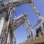
Pressure Dynamics was engaged to modify the hydraulic systems of four LNG marine loading arms in 2019.
The purpose of the modification was to prevent all four marine loading arms having to be taken out of service when only one marine loading arm required hydraulic maintenance work. Installation of isolation valves to segregate each marine loading arm is further considered appropriate for asset and system safety.
Marine loading arms are an integral part of an LNG gas plant. They are the fluid transfer mechanism which transfers the LNG at temperatures below 160 degrees Celsius from the dock to the floating transport vessel.
Approach
The four marine loading arms are powered by a common hydraulic power unit. At each of the arms the common hydraulic line branched off to provide fluid power required for its movement. At each arm branch a compact series of tubing routed the fluid under pressure to its respective function on the arm.
The approach to adding these isolation valves to each of the four arms was to start with a laser scan survey of each of the arms. This was to capture the precise location in 3D of each of the existing hydraulic tubes and support structures.
Following this 3D scan and site survey, four weeks of drafting commenced to create the accurate dimensional drawings of required tube runs for installation of the 14 new isolation valves and 15m of tubing for each marine loading arm.
Once the detailed drawings of the tubing had been completed, the 3/4″ and 1/2″ hydraulic tubes made of 316 stainless steel material were fabricated at Pressure Dynamics’ workshop, and subsequently flushed and leak and pressure tested pre-installation.
While this was underway, the Pressure Dynamics engineering department developed work packs detailing step by step how to safely install the new tubing and isolation valves on-site. The key areas of the work pack included: isolation of the existing system which operated under high pressure. The following steps then detailed the installation steps to safely remove old tubing and install the new components. Commissioning steps then detailed how the complex system of hydraulic tubes and valves could be checked that installation had occurred correctly.
Results/Benefits
Through Project Management from Pressure Dynamics, the modifications to the four loading arms were successfully completed on-site in 72 hours working around the clock. This was a major success for the client who requires maximum availability of the loading arms to deliver LNG to their clients. The figure below shows a 3D model of some valves installed in the tight spaces at the arm. Different colours were used to communicate the various functions each line was used for in the 3D model.
Conclusion
This case study demonstrates Pressure Dynamics proficiency in delivering projects for critical Oil & Gas systems.
Pressure Dynamics Project Managed the job from end to end including the 72-hour rapid on-site installation on the four loading arms in-between LNG marine loading operations.
The use of technology to 3D laser scan and 3D model the solution increased the quality and reduced the lead time required to complete the job.

