Situation
A crane inspection and fatigue life study is essential to assess a crane’s suitability for continued safe use.

A crane inspection and fatigue life study is essential to assess a crane’s suitability for continued safe use.
Gantry cranes require major inspection and fatigue life study to determine its safety and lifespan.
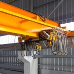
Pressure Dynamics mobilised crane technicians to perform a 12-month crane inspection as per Overhead, Jib, Gantry and Monorail Crane Condition Checklist and a fatigue life study on 10t gantry cranes.
The inspection and study conducted on the individual cranes provided critical information on the safety and suitability for continued use.
The risk assessment of Pressure Dynamics’ Crane Technicians captured probable compliance issues and safety hazards and specified recommendations to be implemented for the indicated timeframe.
Pressure Dynamics mobilised a crane technician to perform a 12-month crane inspection in accordance with the Overhead, Jib, Gantry and Monorail Crane Condition Checklist and a review of previous crane inspection reports.
The life extension study was conducted on another 39-year-old crane with unknown design standard. The study aims to justify the life cycles and fatigue life years and provide recommendations. This would confirm that the crane is able to withstand the number cycle of stress experienced throughout crane life operation and justify the fatigue life from current to the end of life.
The 12-month crane inspection includes the assessment of the crane’s certification, support structure, bridge beams, cross-travel trolley, long-travel drive assembly, cross-travel drive assembly, main hoist, main wire rope, main hook, lubrication, electrical system and functional checks. Following the inspection, previous reports were reviewed and evaluated based on Section 7.3.4 of AS 2550.3-2002. This states that major inspections shall include the following:
The study on the crane life extension followed the workflow below to achieve the fatigue life of the crane structural path:
A 3-Dimensional computer structural model of the crane was created in SpaceGass by positioning spatial nodes representing structural intersections and connecting them with beam elements representing the actual section sizes and properties of the members used. The plateworks are modelled with plate element function in SpaceGass.
Fatigue design loads were determined according to AS1418. Loading tables were set up to calculate the design loads to be applied to the structural models. The loading considered the dynamic factor which takes into account of the following:
A moving load along the crane girder was performed and worst load case position determined.
Additional vertical and horizontal design load components due to inertia, brake, cross travelling, longitudinal travelling and oblique travelling were applied to the model to simulate the crane motion.
The self-weight of the crane was included by applying a gravity load to the structure.
The complete modelling snapshot of the crane includes the crane bridge girder, end carriage and representation of part of the runway beam.
The Rainflow Counting Method was used in the fatigue analysis to reduce a spectrum of varying load into a set of predetermined load ranges which then allows the application of the Miner’s Rule to assess the fatigue damage ratio of the crane subjected to complex loading.
By iteration of the load and forces, it is noted that the critical stresses acting on the crane structure is when the trolley hoist is at approximately a 3rd of the girder length. Principal Stress σ1, Principal Stress σ2 Max Shear Stress τ were obtained from the SpaceGas model.
The principal stresses give the maximum and minimum normal stresses on the particular element which is used to determine maximum stress range for fatigue analysis. The maximum principal stresses range on the crane is observed to be on the top plates of the end carriage structure.
Upon proper inspection and review of the preceding inspection reports and recertification, it was found to be lacking critical assessments and previous recommendations have not been addressed. Pressure Dynamics presented a risk assessment that captures all outstanding items and outlines recommendations to repair faults along with a timeframe for completion. To be able to maintain the crane’s life extension recertification, all recommendations must be implemented and a subsequent risk assessment should be conducted.
A 3-dimensional model of the second crane was created and analysed using SpaceGass, with design loads calculated in accordance with AS1418. The crane was commissioned 39 years ago, and the standard utilised to manufacture the crane was unknown. AS3990 and AS4100 have been followed to analysed fatigue life joints as pointed in AS1418. This study was carried out on the presumption that the non-primary steel parts of the crane (crane walkway, building structure, etc.) and mechanical part of the crane (trolley, hoist, etc) are maintained as part of the PMR of the crane and not part of this scope of work.
Based on the study, the crane steelwork utilisation at maximum stress area is at 28%, not considering bolt connection details. This gives a generous life span of the crane structure and is acceptable for further 5 years of operations provided that they follow specified recommendations.
The inspection and review of previous crane reports was able to assess the first 10t gantry crane’s suitability for continued safe use while the life extension study identified the critical members for the fatigue life of the 10t gantry crane.
On both cases, Pressure Dynamics was able to provide detailed recommendations based on standardised compliance checklists and innovative structural engineering software models.
This case study demonstrates Pressure Dynamics’ proficiency in conducting gantry crane inspections and modelling and analysing data for a crane life extension study.