Situation
Damage to structural members of an offshore pedestal crane boom was identified during an inspection.

Damage to structural members of an offshore pedestal crane boom was identified during an inspection.
Client required a structural analysis to assess physical damage to the crane boom members identified, and determine whether the Safe Working Load (SWL) of the crane needed to be de-rated.
Pressure Dynamics created a 3-dimensional model of the boom with reference to reference drawings and engineering documentation.
Design loads were determined according to API 2C 7th Edition, and with reference to sea conditions and combined input factors.
SpaceGass analysis results were checked against AISC ASD for structural utilization, and also against AS4100.
It was found that although the physical damage to the crane boom members increases the maximum utilisation of the boom, it was still within the allowable limits of AISC requirement. Pressure Dynamics further recommended monitoring, maintenance and operational management actions, supporting scheduled and cost-effective maintenance planning.
The client achieved confidence in ongoing lift operations and confirmed operational compliance for the asset and facility
Pressure Dynamics was engaged by the client to conduct an analysis of the structural effects of damage identified during a prior inspection on the offshore pedestal crane, to determine whether the Safe Working Load (SWL) specified in its load chart needed to be de-rated.
Prior to the structural modelling and analysis, a crane inspection and Hardness tests and dimension inspection for the steel sections was conducted on site to obtain Rockwell B number (HRB). The HRB numbers were converted to the steel tensile strength.
A 3-dimensional model of the boom structure was created was modelled according to the geometry and properties detailed on the reference drawings and engineering documentation.
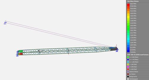
The models were created in SpaceGass by positioning spatial nodes representing structural intersections and connecting them with beam elements representing the actual section sizes and properties of the members used. In this instance the boom foot nodes were restrained in x, y planes for rotation thus acting as a pivot point. The nodes at top of the boom hoist rope are restrained in the same manner as the boom foot pins. The boom tip pin elements at the cathead were represented by adding extra members to support the sheave shafts.
Design loads were determined according to API 2C 7th Edition: 2012 “General Method”. Loading tables were set up to calculate the design loads to be applied to the structural models.
The vertical dynamic coefficient factor Cv (2.4 from the crane load chart) to take account of the following:
The vertical and horizontal design load components were applied to nodes representing sheave locations at the boom head on the SpaceGass model. Sidelead and offlead were applied to the model to simulate the crane motion, the supply boat motion and the wind conditions.
The self-weight of the boom was included by applying a gravity load to the structure. Wind loading was included using a wind speed of 40mph (17.88m/s) throughout as stated in the crane load chart. The loads were applied to the structural model and the analysis was run for the 4-fall configuration for the following conditions:
The boom deflects to one side and down due to side loading from the wind load, crane sidelead due to supply boat movement and vertical loading from the main load.
The defects identified in the crane inspection were reviewed – the analysis process was completed by taking a worse case in which all the damaged members were removed in the design analysis.
This modelling presumes that apart from the damage specifically identified in the inspection report, the structural and mechanical components are in their as-built state, corresponding to the drawings supplied by the Original Equipment Manufacturer (OEM).
Relevant sea conditions are defined as:
Offboard lifts at 3.0m SWH with Dynamic Factor (Cv) of 2.4 for 4 parts of line crane configuration from which the respective safe working load is determined to specify API 2C design loads. The design loads were then applied to each SpaceGass Model as follows:
Combined factors modelled and assessed included:
All structural members in the SpaceGass model were checked against AISC ASD in the SpaceGass analysis for structural utilisation. The model was simulated for all crane radius position and results were checked. The model was also checked and found satisfactory accordance to Australian Standard AS4100. (The AS4100 result is less conservative than AISC ASD requirement based on the member stress results.)
It was found that although the physical damage to the crane boom members increases the maximum utilisation of the boom, this is still within the allowable limits of AISC requirement.
The structural members are acceptable given that the model was ‘damaged’ (affected members removed from the model) to a larger extent than the structure was, therefore, no de-rating is required.
Pressure Dynamics further recommended monitoring, maintenance and operational management actions, which included:
This case study demonstrates Pressure Dynamics proficiency for conducting structural modelling and analysis in compliance with API 2C 7th Edition: 2012 and AISC ASD.