
Pressure Dynamics was engaged to troubleshoot repeated uncontrolled load-lowering incidents on an FPSO port crane’s auxiliary winch after prior attempts by other contractors and the OEM failed to find a solution. The team built a comprehensive digital twin model of the crane’s hydraulic, electrical, controls and HMI systems, calibrated with real-world operational data gathered offshore, and replicated the fault in simulation to identify the root cause as incorrect counterbalance valve configuration. With engineered corrections modelled and tested virtually, Pressure Dynamics sourced and installed the required components, then recommissioned the crane for safe, reliable operation.
‘Digital Twin’ Modelling, Simulation, Analysis & Troubleshooting
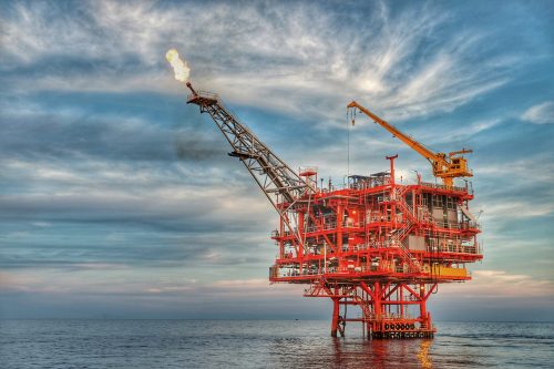
Situation:
Numerous uncontrolled load-lowering incidents had been experienced on the auxiliary winch of the FPSO port crane.
2 other contractors and the OEM had failed to identify the root cause of the fault.
Problem:
Without a functioning port crane, ongoing safe and commercial FPSO operations were at risk.
The client required an alternate basis to troubleshoot the root cause of the uncontrolled load-lowering incidents.
Solution:
Pressure Dynamics modelled the hydraulic, electrical, controls and HMI (human machine interface) of the crane in its Multi-functional ‘digital twin’ modeling, simulation, analysis, and troubleshooting technology.
A Senior crane technician was mobilised to the FPSO offshore of West Africa to investigate the operations of the crane; that operational data then used to calibrate the ‘digital twin’ model. Desktop troubleshooting of the root cause was conducted in the model, the existing fault was replicated in simulation, and the rectification engineered, modeled, and simulated.
Benefits:
Pressure Dynamics identified the root cause of the system fault, which was a design fault in the original manufacturing of the crane.
Componentry to rectify the fault was sourced and manufactured by Pressure Dynamics and mobilized to the FPSO.
Pressure Dynamics’ crane technician installed the componentry and modified the crane, then tested and re-commissioned the crane for fault-free, safe operations.
Overview:
Numerous uncontrolled load-lowering incidents had been experienced on the auxiliary winch of the FPSO port crane.
2 other contractors and the OEM had failed to identify the root cause of the fault.
Approach:
The Pressure Dynamics Lead Crane Technician mobilised to the FPSO with a data logger, flow meter and hydraulic oil patch test kit to conduct a series of fault-finding activities.
In parallel, the Pressure Dynamics Hydraulic Systems Engineer simulated the hydraulic system in our Multi-functional ‘digital twin’ modeling, simulation, analysis, and troubleshooting technology utilising the data recorded by the Technician to assist in determining the root cause of the uncontrolled load lowering incidents.
The root cause was determined to be the installation of a counterbalance (CB) valve with an incorrect pilot control ratio.
Root Cause 1 – Incorrect pilot ratio of CB valve
When Pressure Dynamics checked the CB valves on the port auxiliary crane it was set to 244 bar.
With the pressure set at 287 bar (Ppressure setting) as recommended by the OEM , a pressure of 150 bar between the motor and CB valve with SWL on the hook (P¬load max), a pilot ratio of 5 ® and the factor of difference between the actual and theoretical pilot pressures taken from the starboard crane CB valve of 6 bar (Pact-diff); the minimum pilot pressure (Ppil min) required to open the CB valve with SWL on the hook is calculated.
Root Cause 2 – Counterbalance valve opening before winch brakes are fully released
Counterbalance valves should be set to open after the static brake is fully released.
The auxiliary winch brake is a Dinamic Oil F906 brake pack which has a brake total release pressure of 22 bar as per Figure 3 below.
During testing it was found that the pilot pressure to open the CB valve ranged from 8 – 21 bar (see Figures 4 and 5) on the port and starboard crane auxiliary winches with loads between 53 – 88 % of SWL.
From both the actual measured and calculated pilot pressures, it is evident that the CB valve opens before the static brake is fully released.
Root Cause 3 – Motor sustaining damage when lowering loads
The CB valve opening before the static brake is fully released causes the pressure in the auxiliary winch hydraulic circuit to fluctuate resulting in the static brakes being applied and released rapidly. This causes the hydraulic motor to rotate in a stop-start manner repeatedly which damages the motor and static brake and creates heat in the system.
Specifically, it does not allow sufficient lubrication to build up on the internals of the hydraulic motor port plate and cylinder barrel face causing mechanical damage. This mechanical damage on the motor port plate and cylinder barrel face increases the more the winch is used; particularly with loads close to the SWL.
During testing it was found that the starboard crane with a 4t load (54% SWL) is currently experiencing this phenomenon. Figure 6 below shows the CB valve (blue line) opening before the static brake (green line) has opened and depicts the resultant cyclic application of the static brake due to pressure fluctuations in the auxiliary hoisting system.
The cyclic application of the static brake was also physically heard by the Pressure Dynamics Lead Crane Technician during this test.
Pressure Dynamics were able to inspect three auxiliary winch motors from the port and starboard cranes and found common damage between them all.
There was significant scoring evident on the port plate and cylinder barrel face and evidence of cavitation. The cavitation is a result of the scoring on the mechanical faces, creating peaks and troughs in the metal, allowing hydraulic fluid to leak out into the case of the motor.
Root Cause 4 – Heavy loads and high system pressure resulting in high motor case drain flow
Due to the crane functions not being individually pressure compensated, when one function is operating at high pressure it makes this high pressure available to all the other functions running on the same pump. Similarly, a higher flow rate is also provided to the other functions than would usually be provided.
During the latest incident, the crane operator had a 6.8t load on the auxiliary hook and was luffing up the boom and hoisting down on the auxiliary winch to land the load on the deck.
As both functions are powered by the same pump, a higher volume of flow than usual is provided to the auxiliary motor which, due to the mechanical damage experienced by the motor, is now able to leak through the case drain.
This high case drain flow is depicted in Figure 7 where the uncontrolled load lowering incident was simulated with a load of 6.6t (88% SWL).
The luffing function required 110 bar to luff up the load whereas the auxiliary winch motor only required 8 bar to lower the load. The pump supplies the higher pressure and flow rate and makes it available to the auxiliary motor. When the auxiliary winch was slowly operated in the down direction whilst luffing up, the case drain flow (dark blue line) spiked to between 15 – 30 L/min.
Root Cause 5 – Increased back pressure in motor case resulting in valve plate lift off and motor free spinning
The high case drain leakage causes back pressure in the motor case to increase and disrupt the forces which normally balance the motor.
If this back pressure is high enough then it can lift the cylinder barrel off from the port plate and allow the motor to free spin which results in the uncontrolled load lowering incidents.
Figure 8 shows how the pressure is normally balanced in the cylinder barrel. The forces shown are:
- F1 – spring force holding the cylinder barrel against the port plate
- F2 – system pressure acting on the cylinder barrel to separate it from the port plate
- F3 – case pressure acting on the cylinder barrel to separate it from the port plate
During normal operation in a healthy motor, the spring pressure (F1) is greater than the pressures acting on the cylinder barrel (F2 & F3); thus, the cylinder barrel and port plate are constantly in contact.
During testing of the port auxiliary winch with 88% SWL, while luffing up and slowly lowering the load, the case drain leakage averaged 15 L/min for 5 seconds and then spiked to 30L/min in the 2 seconds prior to the simulated uncontrolled load lowering event.
These spikes of case drain flow rates would have created the necessary case drain pressure to overcome the spring forces and separate the cylinder barrel from the port plate.
This is evident in Figure 7 where the motor speed increases significantly at the 37 second mark indicating that the motor is free-spinning, and the load is lowering uncontrollably.
Results/Benefits:
During the fault-finding investigation, several hydraulic system, crane operation and OEM specification faults were identified and rectified to return the crane to full functionality. Key issues included hydraulic oil cooler inefficiency, incorrect PLC temperature control settings, and an incorrectly installed cooling circuit modification. Additional mechanical and system faults were identified, including missing check valves on the winch motor case drain, poor hydraulic oil cleanliness levels, water saturation, and potential contamination within the hydraulic system.
Further investigation identified incorrect crane function speeds outside OEM specifications, damage to the brake and sprag clutch components, a missing load sense line orifice causing pressure spikes, and hydraulic hoses operating below required pressure ratings. Pressure Dynamics technicians completed modifications, component replacements, hydraulic oil analysis, system adjustments and OEM specification corrections to improve hydraulic system performance, crane reliability and safe lifting operations.
Conclusion
Pressure Dynamics’ application of Multi-functional ‘digital twin’ modeling, simulation, analysis, and troubleshooting technology and subject matter expertise resulted in identification of the root cause system fault, which was a design fault in the original manufacturing of the crane.
Componentry to rectify the fault was sourced and manufactured by Pressure Dynamics and mobilized to the FPSO.
Pressure Dynamics’ Lead Crane Technician installed the componentry and modified the crane, then tested and re-commissioned the crane for fault-free, safe operations.